

introduced in 1987, VGA provides 640 x 480 resolution color display screens with a refresh rate of 60Hz and 16 colors displayed at a time. If the resolution is lowered to 320 x 200, 256 colors can be displayed. VGA capability is built into plug-in video cards, VGA chips, and monitors that can work with the VGA cards. Today, VGA has been replaced by SVGA.
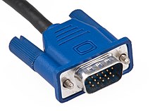
Below is an illustration of the 15-Pin VGA connector, its pin assignments, and size dimensions with a chart describing what each of the pins are for
The same VGA cable can be used with a variety of supported VGA resolutions, ranging from 640×400px @70 Hz (24 MHz of signal bandwidth) to 1280×1024px @85 Hz (160 MHz) and up to 2048×1536px @85 Hz (388 MHz). There are no standards defining the quality required for each resolution, but higher-quality cables typically contain coaxial wiring and insulation which make them thicker. A quality cable should not suffer from signal crosstalk which occurs when the signals in one wire induce unwanted currents in adjacent wires, ghosting which occurs when impedance mismatches cause signals to be reflected (note that ghosting with long cables may not be the fault of the cable but may instead be caused by equipment with incorrect termination or by use of passive splitters), and other signal degradation effects; shorter VGA cables are less likely to introduce significant degradation. Some higher-end monitors and video cards featured 5 separate BNC connectors for RGBHV signal, allowing highest quality connection using five 75 ohm coaxial cables.
Adapters
There are HDMI to VGA and DVI to VGA adapters, and VGA to SCART converters.
In HDMI/DVI to VGA one needs to run a separate audio line.
| Pin out | |||
|---|---|---|---|
  | |||
| A female DE15 socket (videocard side). | |||
| Pin 1 | RED | Red video | |
| Pin 2 | GREEN | Green video | |
| Pin 3 | BLUE | Blue video | |
| Pin 4 | ID2/RES | formerly Monitor ID bit 2, reserved since E-DDC | |
| Pin 5 | GND | Ground (HSync) | |
| Pin 6 | RED_RTN | Red return | |
| Pin 7 | GREEN_RTN | Green return | |
| Pin 8 | BLUE_RTN | Blue return | |
| Pin 9 | KEY/PWR | formerly key, now +5V DC | |
| Pin 10 | GND | Ground (VSync, DDC) | |
| Pin 11 | ID0/RES | formerly Monitor ID bit 0, reserved since E-DDC | |
| Pin 12 | ID1/SDA | formerly Monitor ID bit 1, I²C data since DDC2 | |
| Pin 13 | HSync | Horizontal sync | |
| Pin 14 | VSync | Vertical sync | |
| Pin 15 | ID3/SCL | formerly Monitor ID bit 3, I²C clock since DDC2 | |
| The image and table detail the 15-pin VESA DDC2/E-DDC connector; the diagram’s pin numbering is that of a female connector functioning as the graphics adapter output. In the male connector, this pin numbering corresponds with the mirror image of the cable’s wire-and-solder side. | |||
Computer components:
No comments:
Post a Comment